A guide for engineers and quality professionals in medical device, pharmaceutical, and precision manufacturing.
Engineers working with plastic components, including moulded housings, sealed assemblies, auto-injectors, inhalers, and microfluidic cartridges, regularly encounter inspection problems that standard measurement equipment cannot address. A feature a probe cannot reach. A sealed assembly that cannot be opened without compromising the measurement. A surface too complex for line-of-sight capture. An internal defect with no external signature.
Industrial CT scanning was developed to address precisely these categories of problem. This article sets out what CT scanning delivers for clients with plastic components and assemblies, focused on inspection capabilities.
Where Standard Metrology Reaches Its Limits With Plastic Components
CMMs, optical scanners, and vision systems are effective tools within their operating range. For external features on rigid, accessible components they perform well. Plastic components used in medical devices, drug delivery systems, and complex consumer assemblies, however, routinely present inspection requirements that fall outside that range:
- Internal channels, cavities, and fluid pathways enclosed within the moulded geometry
- Organic, contoured, or freeform outer surfaces that cannot be fully captured through point sampling
- Assembled or sealed components where disassembly changes or destroys the condition under inspection
- Thin walls and flexible geometries that deform under contact measurement force
- Function-critical internal features with no external access for conventional probing
- Multi-component assemblies where internal positional relationships must be verified without dismantling the product
CT scanning captures internal and external geometry simultaneously in a single, non-destructive scan. The output is a complete volumetric dataset: a full dimensional record of every surface, feature, and relationship within the component, covering both internal and external geometry.
Measuring Internal Features and Hidden Geometries Without Sectioning the Component
For many plastic components used in medical devices and drug delivery, the internal geometry is where the functional dimensions are. Internal drug pathway channels must be within diameter tolerance. Enclosed cavities must be correctly formed. Wall sections must hold within specification. Overmoulded insert positions must be verified against external datums.
With contact or optical methods, accessing these features means sectioning the component. Sectioning adds cost, introduces measurement error at the cut face, and removes the part from any further use. A CT scan covers every internal and external dimension from one acquisition, with the component intact.
Application example: A plastic auto-injector body with internal drug pathway channels, an enclosed spring housing, and several overmoulded insert positions. A single CT scan produces full dimensional data for all internal channels, a wall thickness analysis across the complete component, positional data for all inserts referenced to external datums, and a surface comparison against the CAD model covering both internal and external geometry. No sectioning is required.
Complex Surfaces and Freeform Profiles: Complete Coverage
Plastic components in medical devices, FMCG packaging, and consumer products frequently carry organic or contoured surface profiles: ergonomic grip geometries, complex draft angles, performance-critical seal faces, and highly contoured mating surfaces.
Line-of-sight measurement systems share a common constraint: any surface the sensor cannot see cannot be measured. Deep undercuts, internal transitions, and occluded areas create gaps in coverage. For components where those gaps coincide with functional surfaces, the inspection is incomplete by design.
CT scanning generates a full volumetric dataset from a single acquisition. For complex plastic geometries, this provides:
- Surface deviation analysis against CAD across every point on every surface, reported as a colour-mapped deviation output
- Detection of sink marks, warpage, and surface deformation across the full profile, not only the accessible areas
- Measurement of contoured surface features that would otherwise require multiple fixture setups with contact or optical equipment
- Coverage of draft angles, undercuts, and transition radii that are physically inaccessible to contact probes
- Wall thickness distribution across the complete component, identifying thin sections and areas outside tolerance
For new product introduction and design validation, this provides a complete dimensional picture of how the manufactured component relates to design intent, rather than a sampled subset determined by fixture access.
Assembly Inspection: Verifying the Product as Built, Without Dismantling It
Confirming that an assembly has gone together correctly has historically required either a complex external CMM setup, destructive sectioning, or disassembly of the product. For sealed assemblies or components where the assembled condition is the condition of interest, none of these approaches is satisfactory.
CT scanning allows the complete assembly to be inspected in its as-built, as-sealed state:
- Relative positions of all internal components verified without disassembly
- Gaps, interfaces, and clearances between mating plastic and metal parts measured against nominal
- Sealing surface contact and interface geometry confirmed
- Insert positions and component-to-component alignments checked against design datums
- Voids, misalignments, or incomplete assembly conditions identified where no external indication exists
- Wall sections at multi-material interfaces, including overmoulded inserts in plastic housings, measured directly
For components designed to remain sealed throughout their service life, CT inspection is often the only method capable of verifying internal assembly integrity without altering the product.
Application example: A multi-component plastic medical device with a sealed housing, an internal spring mechanism, and an overmoulded trigger component. CT inspection produces a full dimensional report covering all internal relationships, spring seat geometry, trigger insert position, and any voids at the overmoulding interface. The device is not opened and its assembly condition is not changed.
New Product Introduction: Fewer Tooling Iterations, Better Data Earlier
At the NPI and tooling qualification stage, the gap between design intent and manufactured output needs to be understood quickly and completely. Early moulding trials expose tooling issues, shrinkage behaviour, weld line positions, and warpage. Traditional inspection methods require separate measurement campaigns for different feature types, which extends the time needed to build a complete picture and slows the decision-making process for tooling corrections.
CT scanning produces the following from a single scan of a first-off moulded component:
- Internal and external dimensional comparison against the CAD model, from one acquisition
- Wall thickness distribution identifying areas of thinning or variation
- Volumetric analysis confirming material fill and detecting voids, porosity, or incomplete fill
- Weld line and sink mark positions with quantified dimensional impact
- Full-surface warpage and deformation data, showing total deviation from nominal across the entire component
Design, tooling, and quality teams work from a single consolidated dataset rather than assembling results from multiple separate reports. Tooling corrections are based on complete information from the first inspection cycle, reducing the number of iterations needed before a tool is qualified.
Failure Analysis: Establishing Root Cause Before Any Destructive Work
When a plastic component or assembly fails in service, the immediate priority is establishing root cause with traceable evidence, which is a mandatory requirement in regulated industries where a CAPA must be raised. Traditional failure analysis proceeds through sequential destructive steps. Each step carries the risk of disturbing or removing the evidence that the investigation depends on.
CT scanning provides a complete internal picture of the failed component before any destructive work begins. The failure condition is preserved in its original state, documented fully, and available for as long as the investigation requires.
For plastic component failures, CT scanning typically supports:
- Identification of internal cracking, fracture propagation paths, and crack origin locations prior to any sectioning
- Detection of voids, inclusions, or material discontinuities that contributed to the failure
- Assessment of internal assembly misalignment or positional deviation as a contributing factor
- Direct comparison of the failed component against a conforming reference part, with dimensional deviation clearly quantified
- A fully documented evidence base for CAPA reporting, without irreversible steps having been taken
Subsequent sectioning or chemical analysis, where required, is targeted rather than exploratory. Investigations are completed more efficiently and the supporting evidence is of higher evidential quality.
First Article Inspection: Complete Dimensional Evidence From One Source
First Article Inspection of complex plastic components has historically required co-ordinating several measurement methods, managing separate datasets from each, and accepting that a fully complete picture is difficult to achieve without destructive intervention on internal features.
For components where the balloon list includes internal dimensions, CT scanning is frequently the only method that can produce a complete FAI package without sectioning. Internal and external dimensions, surface form, assembly relationships, and material integrity are all captured in a single scan and reported from a single dataset. The report can be structured directly to the FAI format required by the quality system.
CT as a Master Dataset: Correlating Inspection Systems Across Multiple Sites
One of the most demanding challenges in global manufacturing is maintaining consistent, comparable measurement results across multiple production sites, where different inspection equipment, different software platforms, and different operators are all measuring the same component to the same drawing. Without a common reference, each site produces results that are internally consistent but cannot be reliably compared to one another. Dimensional decisions made at one facility cannot be validated against data from another.
CT scanning addresses this by providing a single, complete master dataset for the component. Because CT captures every measurable feature of the part in one acquisition, the CT dataset can serve as the reference against which all other inspection systems, at any site, are correlated. Deviations between what a CMM or vision measurement machine reports and what the CT master records are quantified, understood, and documented. The correlation is traceable, structured, and repeatable.
Coordinating this type of programme across multiple sites and multiple measurement technologies is where the real complexity lies. The measurement plan, the feature selection, the datum scheme, the reporting format, and the acceptance criteria must all be aligned across every system involved in the programme, regardless of equipment manufacturer or software platform. A CMM running one metrology software package and a VMM running another must both be executing the same measurement intent, in the same sequence, against the same nominal data. If they are not, the correlation exercise measures the differences between programmes rather than the differences between parts.
This alignment is the critical challenge, and it is one that is frequently underestimated. Measurement programmes written independently for each system by each site tend to diverge in ways that are not immediately visible: different feature fitting algorithms, different filter settings, different datum establishment sequences, different point densities. Each difference introduces a source of variation that is attributed to the parts rather than to the measurement process. The result is inter-site disagreement that cannot be resolved without first standardising the measurement approach.
Verus co-ordinates this process end to end. Our role is to establish the CT master dataset, develop the standardised measurement plan that defines exactly what is measured, how it is measured, and how results are reported, and then deploy that plan across every system and every site in the programme. Where equipment differences require adaptation, we ensure that the underlying measurement intent is preserved and that any necessary adjustments are documented and their impact on correlation is understood.
Having CT capability on site is central to how we deliver these programmes. It means Verus controls the master dataset directly rather than depending on a third party. We generate the reference data, we develop the measurement programmes, and we manage the correlation process. The entire workflow sits within one organisation, which removes the co-ordination delays and data integrity risks that arise when the CT scanning, the programme development, and the site deployments are handled by different parties.
For clients with components manufactured across multiple locations, or with inspection requirements that span more than one measurement technology, this end-to-end capability is the practical difference between a correlation programme that produces reliable, usable data and one that generates disagreement without resolution.
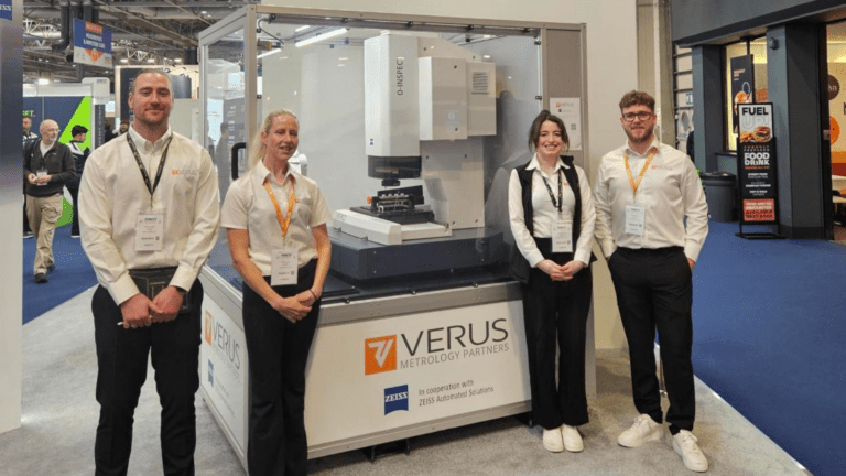
Working With Verus Metrology for CT Scanning
Verus Metrology Partners provides CT scanning as part of an integrated dimensional metrology service. Our measurement engineers have direct cross-sector experience in medical device, pharmaceutical, and precision manufacturing applications, and work with clients on the inspection objective rather than focusing solely on equipment operation.
Verus holds INAB ISO 17025 accreditation (Registration No. 429T) for dimensional metrology services, covering our metrology fixtures and
For clients in regulated industries, working within this quality framework means:
- CT scanning results supported by calibrated, traceable measurement practices and documented uncertainty
- CMM-based dimensional verification delivered under INAB ISO 17025 accredited scope where required
- Reports structured to meet the evidence requirements of regulated quality systems and regulatory submissions
- Integration of CT scanning with our wider accredited metrology capability, including CMM, optical, and surface measurement, to deliver a complete inspection solution
- Consistent capability across 29 countries, with accredited CMM services available at our head office in Sligo
- Reporting formats compatible with your quality management workflow
Our CT scanning service is well suited to clients working with plastic components, sealed assemblies, and medical devices where internal geometry, assembly integrity, or complex surface form is central to product performance.
Evaluating an In-House CT Scanner?
If you are considering capital investment in an industrial CT scanning system, the selection and implementation process involves detailed technical decisions: hardware specification, voxel performance benchmarking, scan protocol development, software selection, and total cost of ownership. These are areas that warrant careful assessment before any commitment.
Verus partners with ZEISS, a leading manufacturer of industrial CT scanning systems. For clients at the capital evaluation stage, ZEISS is the appropriate source for detailed technical guidance on system specifications, capabilities, and acquisition considerations. We direct clients there without hesitation for that level of technical detail.
For clients who want to establish what CT scanning can deliver for their specific components and processes before committing capital, Verus offers a scanning and inspection service using calibrated, traceable equipment within our quality management system. You receive dimensional results on your own parts, which provides a sound basis for any subsequent investment decision.
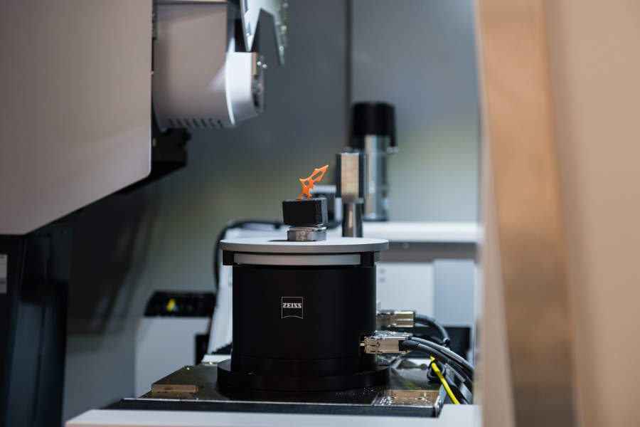
Fixturing for CT Scanning: Ensuring Repeatable, Reliable Results
For CT scanning to deliver consistent and reliable measurement data, the way a component is held during scanning is critical. This is particularly important for plastic components and assemblies, where parts may be lightweight, flexible, or sensitive to deformation.
Unlike traditional metrology, where fixturing is primarily used for access and positioning, CT scanning requires the component to remain completely stable throughout a full rotation during data acquisition. Any movement, even at a very small scale, can affect the quality of the scan and the reliability of the resulting measurements.
Stable Positioning for Consistent Results
Custom fixturing ensures that components are held securely and remain stable throughout the scan cycle. This is especially important for:
- Thin-walled or flexible plastic parts
- Small or low-mass components
- Assemblies with multiple internal elements
By preventing movement or vibration during scanning, fixturing supports consistent, repeatable measurement results across multiple scans.
Repeatable Setups Across Batches and Projects
For many applications, particularly First Article Inspection, validation activities, or ongoing production support, parts need to be scanned multiple times under consistent conditions.
Custom metrology fixturing enables:
- Repeatable positioning and orientation of parts
- Consistent alignment relative to the scan volume
- Reduced dependence on operator setup
This ensures that results are comparable across batches, time periods, and even different programmes.
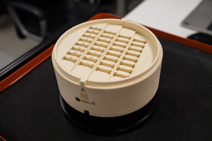
Enabling Efficient Batch Scanning
CT scanning can be used to inspect multiple components within a single scan to improve efficiency. However, this requires careful control of how parts are arranged and held.
Well-designed fixturing allows for:
- Secure placement of multiple parts without movement
- Consistent spacing and orientation
- Reduced risk of overlap or interference between components
This supports higher throughput while maintaining measurement quality, particularly for smaller plastic components produced in volume.
Protecting Delicate and Complex Components
Plastic components often include fine features, thin sections, or compliant materials that can deform under pressure or handling. Fixturing must support the part without introducing distortion.
Custom solutions can be designed to:
- Distribute support evenly across the component
- Avoid contact with critical features
- Maintain the part in its natural, undeformed state during scanning
This is particularly important when measuring functional features or when results are used for validation or regulatory purposes.
Reducing Setup Time and Rework
Standardised fixturing simplifies the setup process and reduces variability between operators. This leads to:
- Faster and more consistent scan preparation
- Reduced need for repeat scans due to setup issues
- More efficient overall inspection workflows
For organisations using CT scanning as part of regular inspection or development activities, this can have a measurable impact on both turnaround time and resource utilisation.
In practice, fixturing is not a secondary consideration in CT scanning. It is a key part of the measurement process that directly influences data quality, repeatability, and efficiency.
For plastic components and assemblies, where stability and consistency are critical, well-designed fixturing ensures that CT scanning delivers reliable and actionable inspection results.
Summary
CT scanning is not suited to every inspection problem, and we will advise honestly when another method is more appropriate. For plastic components and assemblies where internal geometry must be measured, sealed products cannot be dismantled, surfaces are too complex for standard measurement access, or failure analysis requires evidence to be preserved, CT scanning provides dimensional data that other methods cannot.
The practical question for any client is this: which inspection problems on your plastic components are currently being worked around because conventional measurement cannot reach the features that matter? Those are the applications where CT scanning adds direct value.
Verus Metrology Partners | INAB ISO 17025 Accredited (Reg. 429T) | CT Scanning | Dimensional Metrology | Turnkey Metrology Fixtures and Automation | 29 Countries
To discuss a CT scanning requirement: www.verusmetrology.com