THOUGHT LEADERSHIP | 2026
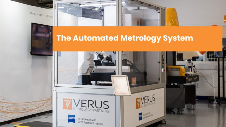
The Automated Metrology System:
What Integrated Inspection Automation Will Mean for Engineers Across Precision Manufacturing
A forward-looking perspective on capability, throughput and process intelligence, from the team at Verus Metrology Partners.
This article is written for the engineering and quality professionals who will lead the transition to automated metrology systems across precision manufacturing industries. It is structured to address each audience’s priorities in sequence.
1. A Turning Point for Dimensional Inspection
Coordinate measuring machine inspection has been the cornerstone of dimensional quality assurance in precision manufacturing for decades. The engineering case for CMM technology is well established: accuracy, traceability, and flexibility across complex geometries. What has not kept pace is the process model surrounding it. Parts are loaded by hand, data is recorded manually, throughput is constrained by operator availability, and measurement capability is capped by human repeatability. That model is being overtaken. Across aerospace, automotive, electronics, medical device, pharmaceutical and FMCG manufacturing, a convergence of robotics, precision part transfer systems, high-resolution metrology platforms and software-driven measurement programmes is making it possible to replace the manual CMM workflow with something categorically different: an automated metrology system in which part handling, measurement and data output operate as a single, unattended, repeatable process. The driver is consistent across sectors, even if the specific tolerance regimes, traceability requirements and validation obligations differ. Whether the challenge is first-off inspection of a complex aerospace structural component, incoming quality screening of electronic connectors at volume, dimensional verification of automotive powertrain parts across multiple cavity tools, or device component inspection in a GMP pharmaceutical environment, the underlying constraint is the same. Manual inspection processes cannot deliver the throughput, the capability or the data density that modern manufacturing demands. This article explores that engineering challenge from multiple perspectives. It draws on the thinking and technical development work underway at Verus Metrology Partners as we advance automated metrology system solutions in partnership with ZEISS, and it reflects the direction we see the industry moving as integration capability matures and deployment confidence grows across the sectors we serve.
PERSPECTIVE
An automated metrology system does not simply replace a manual process. It redefines the performance envelope of inspection: integrating part handling, precision measurement and data output into a single production asset whose capability, throughput and consistency are defined by engineering rather than operator availability or technique.
2. The Automated Metrology System: A Total Solution
Understanding what an automated metrology system is matters before addressing the engineering benefits it delivers. It is not a CMM with a fixture mounted on the table. It is an integrated solution in which every element is designed to work as part of a coherent whole, from the moment a part enters the system to the moment a verified dimensional record leaves it. The system comprises four interdependent components. No single element delivers the performance of the complete solution, and the engineering decisions made in each component directly affect the performance of the others. This is where the design skill lies, and where the capability of the total system exceeds the sum of its parts.
Part presentation and transfer is the element most frequently underspecified in early-stage automation thinking, and the one most likely to limit overall system performance if not treated with the same engineering rigour as the metrology machine itself. Whether the system uses a collaborative robot for flexible part loading, a dedicated end-of-arm tool with vision-guided placement, linear transfer rails for in-line production integration, or a precision indexing carousel for high-volume multi-station inspection, the engineering requirement is the same. The part must arrive at the measurement position in the correct datum orientation, repeatably, every cycle, without exception. The metrology machine (whether a contact CMM, an optical or vision-based system, or a multi-sensor platform such as the ZEISS O-INSPECT combining contact and optical measurement) provides the dimensional measurement foundation. Machine selection is determined by the feature geometry, tolerance regime, surface characteristics and throughput requirements of the specific application. In a well-designed system, the machine is sized and specified for its role in the overall solution, not selected first and worked around. The measurement programme is the intellectual core of the system: the CMM routine, tolerance logic, decision rules and data output structure. It defines which features are measured, in what sequence, with what probe configuration, against what acceptance criteria, and how results are communicated to the operator and quality system. A measurement programme developed without considering the part handling mechanics, the machine’s optimum operating envelope and the downstream data requirements of the quality system will underperform regardless of hardware quality. Programme development and system integration are inseparable engineering activities. The system control and data layer (sequence logic, part traceability linkage, alarm management, SPC data output and MES integration) is what converts a collection of capable hardware and software into a production quality asset. It is also where the data advantage of automated inspection is realised: structured, traceable, per-part dimensional records generated automatically as a consequence of the inspection process, rather than as a separate data entry activity.
ENGINEERING PRINCIPLE
Every system design decision has downstream consequences. The part transfer method constrains the datum scheme. The datum scheme constrains the measurement programme structure. The programme structure determines what data the system generates. Engineering the system as a total solution, rather than specifying each component independently, is what delivers the performance that automated inspection promises.
3. Accelerating New Product Introduction with Automated Metrology Systems
For NPI engineers, inspection is rarely the programme’s primary focus, but it has a consistent capacity to become its bottleneck. First article inspection queues, late-stage measurement capability surprises and MSA studies conducted after transfer rather than before it are structural features of programmes that rely on manual CMM workflows. An automated metrology system designed as part of the NPI programme, rather than appended to it, offers a fundamentally different model.
3.1 FAI at Development Speed
In a manual CMM workflow, first article inspection is serialised by instrument availability and operator time. Parts queue, engineers wait for data, and design iterations are paced by inspection throughput rather than engineering insight. The challenge is common across sectors: in aerospace, the validation of complex machined structure across multiple datum configurations; in automotive, the characterisation of a multi-cavity injection-moulded component across all tool positions; in electronics, the verification of fine-pitch connector geometry at scale; and in medical device or pharmaceutical manufacturing, the dimensional characterisation of precision-moulded components across full cavitation sets. An automated metrology system configured for the component family under development compresses this timeline substantially. A system with a multi-station transfer carousel or robotic loading arrangement can present complete cavity sets or component families to the measurement position in a single unattended sequence. The measurement programme executes the same validated routine on every part. Results are returned as a complete dimensional dataset (not a sample, not a spot check) within the time a manual CMM queue would have been building. For NPI teams, this means measurement data keeps pace with design iteration rather than lagging behind it.
- Reduce FAI cycle time materially through automated, unattended system operation
- Inspect complete component families or cavity sets in a single system cycle
- Generate full dimensional datasets within the NPI programme, not after transfer
- Surface tolerance stack issues during development, before they are locked into production tooling
3.2 Setting Tolerances on the Basis of Real System Capability
One of the less-discussed constraints in NPI is the relationship between component tolerances and measurement system capability. Tolerances are frequently specified based on design intent and functional analysis, then tested against a measurement system whose capability is not fully characterised until the MSA study is conducted. By that point, tolerances have often been committed to drawings, supplier agreements and tooling specifications. Where an automated metrology system is designed into the programme from the outset, this sequence reverses. The system’s measurement capability (quantified through the combined effect of part transfer repeatability, datum location consistency, CMM machine performance and programme measurement strategy) is established during development. Tolerances can then be specified with confidence that the system can enforce them in production. In aerospace, where form and position tolerances on structural features must be maintained to certified limits, this assurance is programme-critical. In automotive and electronics, where part-to-part consistency at volume determines functional performance and assembly yield, it directly affects downstream quality metrics. For pharmaceutical and medical device applications, the system’s measurement capability must not only be sufficient but documented and validated to demonstrate it. Designing the metrology system into the NPI programme means that validation evidence (GR&R studies, measurement uncertainty budgets, installation and operational qualification records) is generated as a natural output of development rather than a retrospective exercise at transfer.
3.3 The Metrology System as a Transfer-Ready Production Asset
Design transfer should deliver a validated metrology system, not a calibrated instrument that still needs qualifying. The complete system (part transfer arrangement, metrology machine, measurement programme, GR&R validation study, measurement uncertainty budget and supporting documentation) developed as part of the NPI programme should transfer as a production-ready asset. This principle applies whether the governing quality framework is AS9100, IATF 16949, IPC standards or ISO 13485 and GMP requirements. The documentation specifics differ; the engineering discipline is the same. The system that validated the design is the system that runs in production. That continuity of hardware, programme, transfer mechanism and datum scheme is a material advantage over programmes that develop measurement approaches during NPI and then rebuild them for production. It eliminates a class of transfer risk that manual workflows routinely carry, and it means the inspection record generated from day one of production is directly comparable to the data generated during development.
DESIGN PRINCIPLE
The automated metrology system is a product of the NPI programme, not an afterthought to it. Designing the system (part transfer, machine, programme and validation documentation) into the development timeline removes a class of late-stage risk that manual workflows consistently carry into production.
4. Measurement Capability: What System Integration Changes
For metrology engineers, the limitations of manual CMM inspection are well understood regardless of sector. Operator-dependent repeatability, the practical ceiling on measurement density, the disconnect between what the CMM hardware can deliver and what the surrounding process actually achieves: these are structural constraints of manual operation, not correctable through procedure alone. An automated metrology system addresses them at the engineering level, by removing the variability sources rather than attempting to control them.
4.1 Capability Engineered Into the System
Manual CMM inspection has an inherent repeatability ceiling determined by how a human loads a part, locates it on a datum, and presents it to the probe. These sources of variation dominate measurement uncertainty on many applications; not the machine itself, but the process surrounding it. The automated metrology system eliminates this. In a well-designed system, the part transfer arrangement (whether robotic end-of-arm tooling, a precision rail and nest, or an indexing carousel) delivers every part to the measurement position within a controlled, repeatable datum envelope. The measurement programme then executes identically: same features, same approach vectors, same probe forces, same dwell times, every cycle. The result is a measurement system whose capability is determined by engineering decisions made during system design, not by operator technique on any given shift. The specific drivers differ by sector. In aerospace, the system must maintain performance on complex surfaces and deep-reach features where stylus deflection variability dominates manual uncertainty. In automotive, consistency across high-cycle-count production runs requires that the transfer mechanism and datum nests are designed to remain stable over thousands of cycles. In electronics, measurement resolution on miniaturised features demands that the combined uncertainty of transfer, datum location and machine measurement is kept well below what manual methods can approach. In pharmaceutical and medical device manufacturing, the system’s capability must be demonstrable through a documented, validated measurement uncertainty budget.
Integrated engineering decisions that define system measurement capability:
• Part transfer design: robot, rail or carousel, with focus on repeatability of part handoff to the measurement position
◦ End-of-arm tooling geometry, grip force and vision-guided placement accuracy
◦ Rail and nest design: guide geometry, stop datum and part release kinematics
• Datum nesting scheme: alignment with the drawing datum framework, constraint method, kinematic versus over-constrained design
◦ Material selection for thermal stability relative to workpiece and environment
◦ Wear criteria and inspection schedule for nesting elements
• Metrology machine specification: contact CMM, optical or multi-sensor, matched to feature geometry, tolerance regime and throughput
• Measurement programme engineering: feature selection, probe path optimisation, point count, scanning versus discrete modes and filtering
• System control integration: sequence logic, part traceability linkage, alarm management and SPC data output
• Measurement uncertainty budget: quantified for each critical feature class, accounting for transfer, datum and machine contributions
4.2 From Point-in-Time MSA to Continuous Capability Intelligence
A conventional GR&R study answers one question: is this measurement system capable today? It provides no ongoing intelligence about whether that capability is sustained as the system ages in production. For manual inspection, this limitation is largely unavoidable. For an automated metrology system, it is an unnecessary constraint on a system that is already generating continuous, structured measurement data as a consequence of normal operation. Because the system executes identically on every cycle, the production data stream is inherently rich in measurement repeatability information. Statistical process control applied to this data allows metrology engineers to detect shifts in system performance (transfer mechanism wear, datum nest degradation, sensor drift, environmental influence) before they affect inspection decisions. This transition from periodic MSA confidence to continuous capability assurance is not additional quality overhead; it is a consequence of the system architecture, available without extra effort once the monitoring framework is defined. Systems can also be configured to measure reference artefacts at defined intervals as an integrated performance verification: an independent, in-cycle check of measurement stability. This is particularly valuable in aerospace applications with long production gaps between repeat components, and in pharmaceutical environments where regulatory frameworks require demonstrated ongoing measurement system performance.
4.3 The Engineering Dividend
Deploying an automated metrology system for routine, high-volume dimensional verification frees experienced metrologists from tasks that do not require their expertise, and concentrates their capability where it generates the most value: developing novel measurement strategies for new geometries and advanced materials; investigating unexpected process variation through multi-variable measurement studies; supporting supplier dimensional capability assessments; and resolving disagreements between incoming, in-process and outgoing measurement methods. This dividend is relevant in every sector, but particularly in aerospace and precision automotive manufacturing, where measurement challenges on complex structural geometries, advanced alloys and tight form tolerances require genuine measurement science expertise. Automated metrology creates the operational capacity for that expertise to be applied to the problems that justify it.
CAPABILITY NOTE
The measurement capability of an automated metrology system is the aggregate of its transfer repeatability, datum location consistency, metrology machine performance and programme measurement strategy. Engineering these elements together, as a system, delivers measurement uncertainty substantially below what manual CMM workflows achieve on the same components.
5. Throughput, Yield and the Data Advantage
Viewed through a process improvement lens, manual CMM inspection has three structural weaknesses across precision manufacturing: it is slow relative to production rates, its detection capability deteriorates as tolerances tighten, and the data it generates is too sparse and inconsistent to support meaningful statistical process control. An automated metrology system addresses all three, and the commercial case for doing so differs by sector in instructive ways.
5.1 Throughput: Unattended, Continuous System Operation
In manufacturing environments running at volume (automotive body and powertrain components, electronic connector and PCB assemblies, pharmaceutical packaging and device components, FMCG consumer product parts) manual CMM inspection is almost always a flow constraint, either explicitly when a backlog of parts awaits measurement, or implicitly when sampling rates are reduced to manage workload. The throughput of manual measurement does not scale proportionally with production volume. An automated metrology system operates on a different model entirely. The part transfer arrangement (robot, rail or carousel) presents components to the measurement position without operator intervention. The measurement programme runs. Results are captured and communicated. The transfer system collects the measured part and presents the next. The operator’s role reduces to batch loading and unloading; everything between those actions is unattended. For multi-station system configurations capable of presenting multiple parts per cycle, the throughput improvement is not incremental on manual rates. It is a step change in inspection capacity. For high-volume automotive and electronics applications, this step change determines whether 100% inspection is economically viable. For pharmaceutical and medical device manufacturing, it determines whether the inspection process keeps pace with batch release requirements. For aerospace, where individual component value is high but volumes are lower, the benefit manifests differently: the system enables more comprehensive characterisation per component (more features, tighter measurement density, richer datasets) within the same or shorter elapsed time than manual methods allow.
5.2 Yield: Detection at the Tolerance Boundary
The relationship between measurement uncertainty and effective yield is direct and consistent across sectors. Where measurement uncertainty is a meaningful fraction of the component tolerance, defects within the uncertainty band pass through inspection undetected. The inspection process has not failed; the measurement system is simply not capable of resolving the non-conformance at the tolerance boundary. In an automated metrology system, measurement uncertainty is the aggregate of the transfer arrangement’s positional repeatability, the datum nesting consistency and the metrology machine’s measurement performance, all engineered together to be small relative to the tolerance. This aggregate capability is substantially better than manual CMM workflows on the same components, and it is consistent. The system does not have good days and less good days based on who is operating it. Effective inspection capability at the tolerance boundary is stable, predictable and documentable. The commercial consequence differs by sector but is compelling in each. In automotive assembly, dimensional non-conformance in powertrain or structural components propagates to fit, function and warranty claims. In electronics, fine-pitch geometry outside tolerance results in soldering failures and field reliability problems. In aerospace, variation in structural or safety-critical components is a certification matter. In pharmaceutical and medical device assembly, component non-conformance can affect drug delivery performance and patient safety. In every case, the economics of improving detection capability at the tolerance boundary are favourable when calculated against the cost profile of failures that current inspection is passing.
What the automated metrology system changes in the process improvement model:
• Throughput: unattended system operation decouples inspection capacity from direct labour hours
• Capability: combined transfer, datum and machine uncertainty engineered to enforce specified tolerances reliably
• Coverage: 100% component screening becomes economically viable, replacing sampling-based inspection
• Data density: full dimensional datasets per part, per batch, per supplier, every cycle, automatically
• Process intelligence: SPC on system measurement data provides early warning of process drift at source
• Consistency: system performance is determined by engineering, not operator variation, stable across shifts, weeks and years
5.3 From Inspection Records to Process Intelligence
The data generated by an automated metrology system is qualitatively different from manual CMM measurement output. Every part the system inspects produces a structured dimensional record: feature coordinates, measured values, deviations from nominal, pass/fail status, timestamps and part and batch traceability. These records are generated automatically as a consequence of the inspection process, not as a separate data capture activity. In automotive manufacturing, dimensional trend data from system inspection can predict tooling wear and support preventive maintenance decisions before non-conforming product is made. In electronics, measurement data correlated across supplier batches identifies process shifts at the source before they reach the assembly line. In aerospace, component characterisation data becomes part of the digital thread, supporting structural analysis, maintenance planning and through-life performance management. In pharmaceutical manufacturing, batch-level dimensional data supports continued process verification and provides the statistical evidence base that regulatory frameworks increasingly require. For organisations pursuing Industry 4.0, digital manufacturing or continuous improvement frameworks across any sector, this data infrastructure is foundational. Decisions about supplier qualification, tooling investment, process capability development and quality system maturity can be made on the basis of actual measurement data at scale, rather than periodic audit samples or operator-recorded spot checks.
6. System Validation as Engineering Assurance
Quality professionals approaching automated metrology system deployment will recognise that a structured qualification and validation programme is required. The specific framework differs by sector: IQ/OQ/PQ under ISO 13485 and GMP requirements in medical device and pharmaceutical manufacturing; PPAP and MSA under IATF 16949 in automotive; FAI qualification under AS9100 in aerospace; process qualification under IPC standards in electronics. Across all of them, the underlying engineering discipline is consistent, and it applies to the complete system, not to individual components in isolation. This is the point most frequently missed in early validation planning for automated metrology systems: the scope of validation is the system, not the CMM. The transfer arrangement, the datum nesting components, the measurement programme logic, the system control software and the data output interfaces are all contributors to the inspection decision and are therefore all within the validation boundary. Limiting validation scope to the metrology machine alone leaves the majority of the system’s capability, and the majority of its failure modes, unaddressed.
6.1 Defining the System Validation Boundary
The validation boundary of an automated metrology system should be defined from the point at which a part enters the system to the point at which an inspection record leaves it. Everything within that boundary that can affect inspection decisions is within scope: the transfer mechanism and its positional repeatability; the datum nesting components and their wear characteristics; the measurement programme logic and its tolerance application; the system control software and its decision and communication functions; and the data output interfaces and their integrity. Defining this boundary explicitly at the outset of validation planning prevents two common failure modes. Under-validation occurs where significant capability contributors are excluded from scope and become sources of unmanaged risk. Over-validation occurs where effort is applied disproportionately to low-risk elements while higher-risk contributions go unaddressed. A risk-based scope definition, identifying which system components have the greatest influence on inspection outcomes, provides the rational basis for allocating validation effort correctly.
6.2 Installation Qualification: The System Baseline
Installation qualification confirms that the complete system (transfer mechanism, metrology machine, measurement programme, control software and interfaces) has been assembled, installed and configured in accordance with its design specification. For an automated metrology system, this is a broader scope than qualifying a standalone CMM. It encompasses mechanical installation and alignment of the transfer arrangement, software configuration and version control across all system components, datum nesting verification against design specifications, interface connection and communication verification, and environmental condition assessment for the system’s deployment location. The IQ output is a documented, traceable record of the complete system as installed. This baseline enables structured change management throughout the system’s operational life. Any proposed modification (to the transfer mechanism, a datum nest component, the measurement programme, the control software, or the system’s operating environment) can be assessed against a known, documented configuration. This discipline is straightforward when established at commissioning and expensive to reconstruct retrospectively.
6.3 Operational and Performance Qualification: Proving the System Works
Operational qualification demonstrates that every element of the system functions correctly across its defined operating range: transfer repeatability, datum engagement, measurement sequence execution, tolerance application, pass/fail decision logic and data output. Challenge testing is particularly important for automated metrology systems. Introducing misaligned parts, deliberately non-conforming components or transfer system fault conditions provides assurance that the system’s response to foreseeable abnormal conditions has been tested and documented. For systems operating in production without continuous operator supervision, this assurance is not optional. Performance qualification confirms that the system’s capability under controlled OQ conditions is sustained in real production, with actual part variation, production environment conditions and the accumulated effects of operational cycling across multiple production runs. Where the automated metrology system replaces a manual CMM process, a correlation study during PQ provides the traceability bridge: documented evidence that the system provides equal or superior control of the critical characteristics previously inspected manually.
6.4 Software, Data Integrity and Change Control Across the Complete System
Three areas consistently attract scrutiny across all sector quality frameworks: software validation, data integrity and change control. For an automated metrology system, each must be addressed across all system components, not just the CMM software. Software validation covers the measurement programme logic, the system control sequence software, any vision-based part identification or placement guidance, and the data output and integration interfaces. Each element should be characterised by its risk and complexity, tested proportionately and controlled through a defined change management process. The measurement programme, as the component that directly determines inspection decisions, typically warrants the most thorough validation treatment. Data integrity requirements apply to every record the system generates: transfer system logs, datum engagement confirmations, measurement results, pass/fail decisions and traceability linkages. The system’s data architecture should ensure that records are complete, accurate, attributable to specific parts and batches, and protected from unauthorised modification. The volume of data that automated metrology systems generate (a significant advantage for process intelligence) requires defined data management arrangements to ensure records remain meaningful and accessible across their required retention period. Change control for an automated metrology system must cover all components within the validated boundary: the transfer mechanism and its tooling; datum nesting components and their materials; the measurement programme and its tolerance settings; the system control software; the metrology machine’s firmware and configuration; and the system’s operating environment. A structured change assessment process, determining whether a proposed change affects validated performance and at what scope requalification is appropriate, protects system performance from uncontrolled modification while supporting the operational agility that production environments require.
VALIDATION PRINCIPLE
The scope of automated metrology system validation is the system, not the CMM. Transfer arrangement repeatability, datum nesting consistency, programme logic and data integrity are as much part of the inspection capability as machine accuracy. Validation planning that addresses all system components from the outset is the foundation of a defensible, sustainable compliance position across any sector quality framework.
7. Sustaining System Performance Over the Operational Lifecycle
An automated metrology system is a multi-year production asset. Sustaining its performance across product changes, software updates, transfer mechanism wear, datum nest degradation and evolving production conditions requires deliberate engineering management across all system components. The foundations for this management are established during system design and commissioning.
7.1 Ongoing Monitoring Across the System
The data richness of automated metrology enables monitoring strategies that are genuinely informative rather than procedurally compliant. Control charts applied to measurement value trends (not just product accept rates) provide early indication of sensor drift, datum nest wear or environmental influence on measurement performance. Reference artefact measurement at defined intervals provides independent, in-cycle verification of system measurement stability. Transfer system performance monitoring (position repeatability logs, cycle time trends, alarm frequency) provides equivalent early warning for the mechanical elements of the system. The monitoring strategy should be defined at system design, with clear ownership, review frequency and defined response criteria.
7.2 Transfer Mechanism and Datum Nesting: The Critical Lifecycle Variables
In automated metrology system lifecycle management, the transfer mechanism and datum nesting components are the elements most frequently underestimated and the most likely to cause gradual, undetected performance loss. Unlike the metrology machine, which typically has defined calibration and maintenance schedules, the transfer system and datum nests are precision mechanical components subject to the continuous cycling of production use. Robot end-of-arm tooling wears at contact surfaces. Transfer rails accumulate debris and develop positional drift. Datum nest contact faces wear, particularly for high-volume applications where cycle counts into the millions are achievable within a production year. In each case, the effect on part positioning repeatability is progressive and may remain below the threshold of obvious alarms until system measurement performance is meaningfully compromised. Defining inspection criteria, wear limits and replacement schedules for these components, and including them in the system’s periodic review programme, prevents a significant and avoidable category of performance degradation.
7.3 Managing Change Across the Complete System
Automated metrology systems will require changes throughout their operational life: software updates, new product variants requiring programme modifications, transfer tooling changes for new part geometries, datum nesting modifications, metrology machine hardware updates, and changes to the system’s production environment. A structured change assessment process covering all validated system components allows these to be managed without stalling operational needs or inadvertently compromising the performance that has been carefully established. The essential discipline is consistent: assess each proposed change against the validated system baseline to determine whether it affects any component that contributes to measurement performance or inspection decision logic, and determine the appropriate scope of requalification. Routine consumable replacement typically does not require requalification. Programme changes, transfer tooling modifications affecting datum location, or metrology machine firmware updates typically do. This framework, established at the outset and maintained consistently, is the mechanism by which an automated metrology system remains a reliable production quality asset across its full operational life.
8. Where This Is Heading
The engineering capability to deploy automated metrology systems in precision manufacturing is no longer a future state. The constituent technologies (high-resolution metrology platforms, collaborative and industrial robotics, precision transfer mechanics, intelligent measurement programmes and production data integration) are available, mature and increasingly well understood across multiple sectors. What is developing is the integration confidence: the accumulated engineering knowledge of how to bring these elements together as coherent, validated, production-ready automated metrology systems for the specific demands of aerospace, automotive, electronics, medical device, pharmaceutical and FMCG manufacturing environments. Verus Metrology Partners is at the centre of that development. In partnership with ZEISS, we are advancing automated metrology system solutions that bring together ZEISS precision multi-sensor metrology (including the O-INSPECT platform, combining contact and optical measurement in a single system) with application-specific part transfer engineering, validated measurement programmes and documentation frameworks developed for the quality and traceability demands of the sectors we serve. The ZEISS O-INSPECT is particularly well suited to the range of component geometries, surface types and tolerance regimes encountered across our target sectors, and its integration into an automated metrology system (with robotic or rail-based part handling and a fully developed measurement programme) is a significant part of what we will be demonstrating at MACH 2026, where a fully operational system will be running. We look forward to the engineering conversations that follow. For engineers planning to introduce automated metrology systems into their programmes, the strategic questions worth asking now are straightforward: which inspection processes are currently constraining throughput, limiting what tolerances can be enforced, or failing to generate the data your quality system needs? Where would a production-ready automated metrology system (transfer arrangement, metrology machine, measurement programme and validation documentation as an integrated solution) change what your programme can deliver? What would it mean for FAI timelines, production quality and process intelligence if those constraints were removed? The organisations that ask these questions early, and build automated metrology capability into their engineering and quality infrastructure ahead of the production pressure to do so, will have a structural advantage. Inspection, properly engineered as a complete system solution, is not a cost of manufacturing. It is a source of process intelligence, product confidence and competitive differentiation, and that is as true on an aerospace certification programme as it is on an automotive production line or in a pharmaceutical cleanroom.
Explore further with Verus Metrology Partners:
• Technical overview: Automated Metrology System Architecture for Precision Manufacturing — verusmetrology.com
• Sector applications: aerospace, automotive, electronics, medical device, pharmaceutical and FMCG
• Discuss your automated metrology system requirements with the Verus engineering team ahead of MACH 2026
• Request a system feasibility study: part transfer, machine selection, programme scope and validation framework for your application
• Visit us at MACH 2026 — ZEISS O-INSPECT automated metrology system running live, with full part handling, transfer and measurement programme in operation
VERUS METROLOGY PARTNERS LIMITED
ISO 17025 Accredited | Precision Metrology and Inspection Services
verusmetrology.com