The Biggest Challenge Verus + BD have Faced to Date
February 18, 2022
The Biggest Challenge Verus + BD have Faced to Date
February 18, 2022
Share:
Constant innovation and advancing medical device designs are part of the reason Becton Dickinson helps to save the lives of patients every day. We all know the role of safety in new product development. However, testing and Validation solutions are not always as clear-cut as they may seem.
During the new product development stage of the Barricor component, BD was not alone in the challenges they faced with this clever device. From tooling and fixturing to measuring, this component presented many challenges. But consequently provided the best learning experiences the team at Verus has possibly experienced.
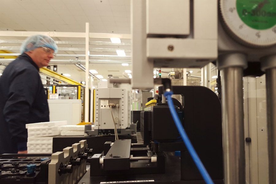
Glen Miller, Senior Metrology Engineer at BD Plymouth was instrumental in the project from the initial contact with Verus, sharing his years of expertise during the fixture POP stage to implementing the final installation on site. Working with the team in Franklin Lakes, including Mukund Patankar, Sr. Staff Engineer, and Mike Ross, Staff Research and Development Engineer, collaboratively found a solution to solve the challenges this component brought.
From Concept to Completion
Verus attended a collaborative meeting with OGP in BD Plymouth to discuss a solution for the Barricore component. In attendance was Glen Miler, Senior Metrology Engineer, Jamie Tabb, Quality Engineer (Projects), and Tom Stimson who was the project lead and finally Graham Shaw from OGP.
Verus proposed a course of action to BD considering the complexity involved in this solution. Along with a proposal on capabilities and timelines, Verus proposed to initiate the project with a test unit.
The proof of principle was successful, and the team quickly got to work on the production fixture.
The BD team placed the order for the vision machine which OGP delivered to Verus in Sligo. Upon completion of the 32-station fixture, the measurement machine arrived. This meant the team could then combine the fixture and the OGP to undertake rigorous testing.
Verus achieved a fill Gauge R&R in Ireland to prove out the fixture and the transfer system. This team could then complete programs collaboratively with OGP. The entire system, Gauge R&R and program were then shipped to BD Plymouth for an on-site install and full MSA.
An initial single station fixture was developed in Franklin Lakes achieving results of sub 30% Gauge R&R. Verus engaged from a production perspective to improve the results. We got it to 15% thanks to the collaborative process to all the team involved as well as Verus’ expertise and capabilities.
As demand ramped up, two repeat projects followed for 128-station versions of the original 32-station fixture. In BD Plymouth currently, there are two 128-station fixtures, one 32-station fixture, and a transfer system. Verus remains in constant communication with the engineers involved in this project as they overcome internal challenges with this component, looking towards the next steps.
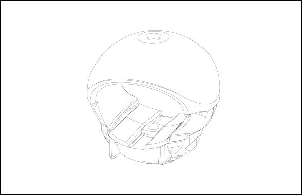
The Barricor Component
The component itself is very complex, intricate, and extremely unreceptive to touch given that it is produced using an exceptionally flexible rubber.
Although the Barricor is minuscule in size, the effect this component has on the process of separating blood and plasma is gigantic. The purpose of the component is to separate the plasma layer. Centrifugation causes the red blood cells to pack at the bottom of the tube with Barricor closely following and providing a barrier between the cells and plasma.
5 Critical Dimensions in 4 Different Positions.
The Barricor must rotate to 4 orientations, in a multi-position situation to access all 5 critical dimensions.
What Challenged verUS The Most?
To ensure the integrity of the measurements, given the nature of the material used, the holding solution must give access to all dimensions needed without compromising the rubber profiles.
From the rubber bung rite down to the chin strap, each profile comprises the rubber material. This proved many challenges from a fixturing perspective. The surfaces also change in geometry as they are rotated. The rubber molds down and around the component and back up.
The A datum is 4 small flat pads on the bottom of the component. Critical to the measurement the A datum stops the part pivoting through its 3 degrees of freedom. The pitch and the yaw control the Z position. It controls the part from spinning or falling. It also controls the position in the direction of the Z height. So, once we know it’s resting on that face and know where the face is, we can then control it.
Measuring The Untouchable
At Verus there is a widely held philosophy, that the fixture is there to hold the part, not to control its position. The team achieves this through innovative design and incorporating flex into the fixture to allow the part to move within reason. Therefore, the machine can then locate the part and attain its datum structure.
However, this was certainly not the case with the Barricor. There was no physical way to hold this component to then access the datum structure. The plastic aspect of this component is the only material that can be held without compromising the geometry of the part. And yes, you guessed it, the datum structure is located in the plastic. With no alternative resolution, the fixture was used in this instance to control all the positioning of the part. That being said, the innovation incorporated into this solution knows no bounds.
Using the fixtures to control the positioning of the component does not come without its challenge when accessing all 5 critical dimensions in a total of 4 different positions. The fixture nests into the modest hollow using pins. However, once you rotate the fixture the component would fall off those pins.
So, what is the solution? The design team at Verus incorporated a small hook to grab into the hollow. This design aspect allowed the part to pull onto the pins because the channel is plastic. This ensures that the part does not gravitate when we rotate by 90-degree increments as it stays pulled onto the pins.
Getting it off the Molding Machine and on to the Fixture
Developing an innovative fixture to hold the Barricor component is only part of the solution. But how do you get the component from the molding machine to the fixture without touching it and causing changes to the part’s geometry?
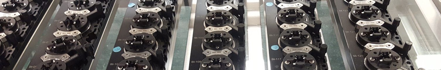
Robotics, Hydraulics, and Transfer Systems
Incorporated beside the injection molding machine is an end-of-arm robot. Originally the robot used beside the cube mold was a 32. The robot offloads 8 components at a time to one of four transfer trays inside the system. The robot replicates the process, filling the 32-stations. There are 4 red lights that look across the rail to make sure the parts are located correctly.
Once this process is complete, outside the cage is a hatch system controlled by a green button. Once pushed it allows you to reach into the robot facility and take the 4 rails. The operator can then move the rails into a base plate and onto the transfer system.
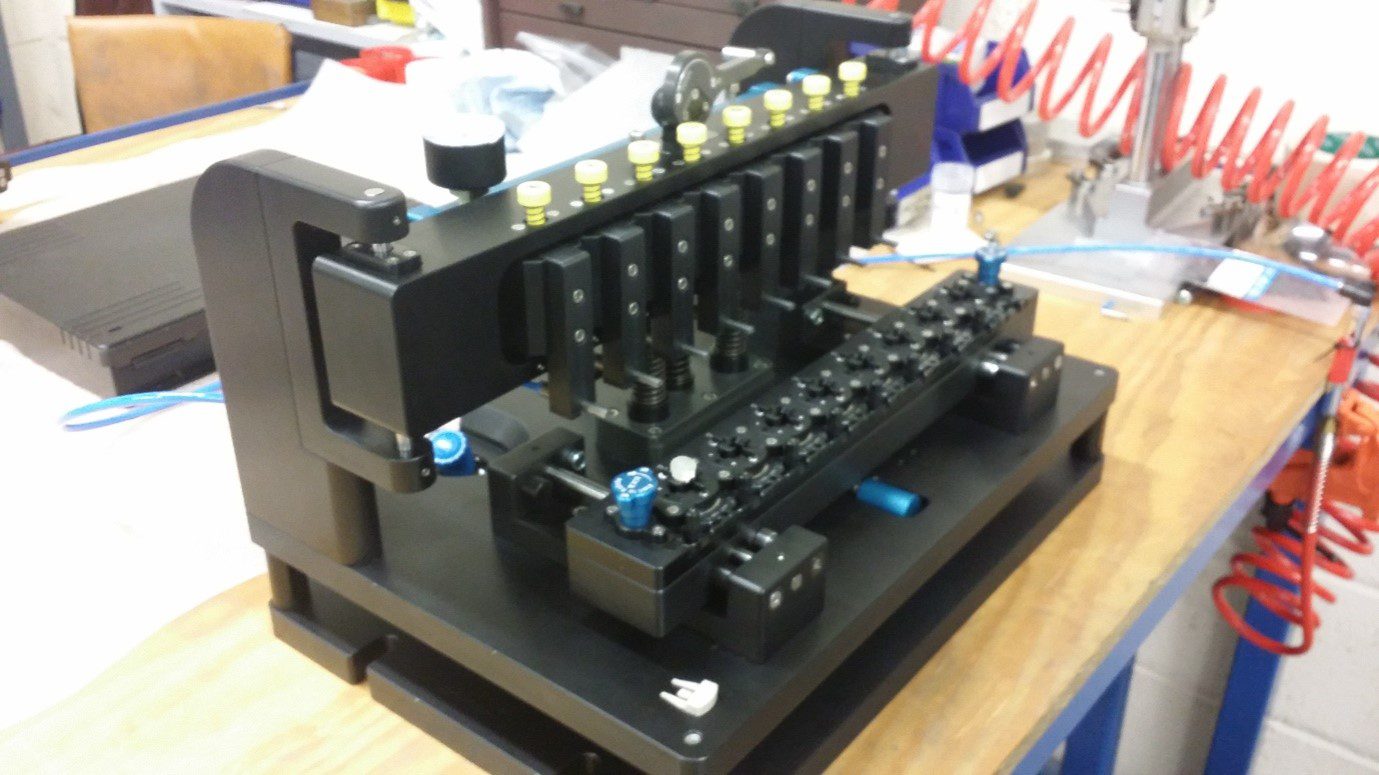
The air pressure gauge is then set at 3.5 bar on the transfer system awaiting the loaded parts.
Using the lifting positions, the robot rail is loaded onto the cross-slide. The operator can then visually check the parts to ensure they are square and located down on their nests. The operator then switches on the air and presses the yellow knobs at the top of the system. The component then visibly lifts out of its nest.
The operator then replaces the robot rail with the empty fixture while the parts float above. Repeating the process in reverse, as demonstrated in the video, until each component is located in the fixture rail. The operator can then confidently move the multi-station fixture to the OGP for measurement. All the while confirming no direct contact with the parts ensuing the component geometry remains unaffected by human intervention.
Why The BD Partnership is so Important to Verus
The long-standing partnership between Verus + Becton Dickinson is based on clarity, communication, trust, and shared expertise. What once seemed like a near-impossible task, these four pillars of our partnership were demonstrated throughout and are the reason for the successful completion of the Barricor project.
To find out more about the Verus + BD partnership, contact our Business Development Manager Tracey Flynn on +353 (0)76 661 9000. To find out more about our turnkey metrology solutions, contact our COO Michael Nugent on +353 (0)71 91 43506 (ext. 215).
We use cookies on our website to give you the most relevant experience by remembering your preferences and repeat visits. By clicking “Accept All”, you consent to the use of ALL the cookies. However, you may visit "Cookie Settings" to provide a controlled consent.
This website uses cookies to improve your experience while you navigate through the website. Out of these, the cookies that are categorized as necessary are stored on your browser as they are essential for the working of basic functionalities of the website. We also use third-party cookies that help us analyze and understand how you use this website. These cookies will be stored in your browser only with your consent. You also have the option to opt-out of these cookies. But opting out of some of these cookies may affect your browsing experience.
Necessary cookies are absolutely essential for the website to function properly. These cookies ensure basic functionalities and security features of the website, anonymously.
Cookie
Duration
Description
cookielawinfo-checkbox-advertisement
1 year
Set by the GDPR Cookie Consent plugin, this cookie records the user consent for the cookies in the "Advertisement" category.
cookielawinfo-checkbox-analytics
11 months
This cookie is set by GDPR Cookie Consent plugin. The cookie is used to store the user consent for the cookies in the category "Analytics".
cookielawinfo-checkbox-functional
11 months
The cookie is set by GDPR cookie consent to record the user consent for the cookies in the category "Functional".
cookielawinfo-checkbox-necessary
11 months
This cookie is set by GDPR Cookie Consent plugin. The cookies is used to store the user consent for the cookies in the category "Necessary".
cookielawinfo-checkbox-others
11 months
This cookie is set by GDPR Cookie Consent plugin. The cookie is used to store the user consent for the cookies in the category "Other.
cookielawinfo-checkbox-performance
11 months
This cookie is set by GDPR Cookie Consent plugin. The cookie is used to store the user consent for the cookies in the category "Performance".
CookieLawInfoConsent
1 year
CookieYes sets this cookie to record the default button state of the corresponding category and the status of CCPA. It works only in coordination with the primary cookie.
elementor
never
The website's WordPress theme uses this cookie. It allows the website owner to implement or change the website's content in real-time.
viewed_cookie_policy
11 months
The cookie is set by the GDPR Cookie Consent plugin and is used to store whether or not user has consented to the use of cookies. It does not store any personal data.
Functional cookies help to perform certain functionalities like sharing the content of the website on social media platforms, collect feedbacks, and other third-party features.
Cookie
Duration
Description
bcookie
1 year
LinkedIn sets this cookie from LinkedIn share buttons and ad tags to recognize browser IDs.
li_gc
5 months 27 days
Linkedin set this cookie for storing visitor's consent regarding using cookies for non-essential purposes.
lidc
1 day
LinkedIn sets the lidc cookie to facilitate data center selection.
VISITOR_INFO1_LIVE
5 months 27 days
YouTube sets this cookie to measure bandwidth, determining whether the user gets the new or old player interface.
YSC
session
Youtube sets this cookie to track the views of embedded videos on Youtube pages.
yt-remote-connected-devices
never
YouTube sets this cookie to store the user's video preferences using embedded YouTube videos.
yt-remote-device-id
never
YouTube sets this cookie to store the user's video preferences using embedded YouTube videos.
yt.innertube::nextId
never
YouTube sets this cookie to register a unique ID to store data on what videos from YouTube the user has seen.
yt.innertube::requests
never
YouTube sets this cookie to register a unique ID to store data on what videos from YouTube the user has seen.
Analytical cookies are used to understand how visitors interact with the website. These cookies help provide information on metrics the number of visitors, bounce rate, traffic source, etc.
Cookie
Duration
Description
_clck
1 year
Microsoft Clarity sets this cookie to retain the browser's Clarity User ID and settings exclusive to that website. This guarantees that actions taken during subsequent visits to the same website will be linked to the same user ID.
_clsk
1 day
Microsoft Clarity sets this cookie to store and consolidate a user's pageviews into a single session recording.
_ga
1 year 1 month 4 days
Google Analytics sets this cookie to calculate visitor, session and campaign data and track site usage for the site's analytics report. The cookie stores information anonymously and assigns a randomly generated number to recognise unique visitors.
_ga_*
1 year 1 month 4 days
Google Analytics sets this cookie to store and count page views.
_gat_UA-*
1 minute
Google Analytics sets this cookie for user behaviour tracking.n
_gid
1 day
Google Analytics sets this cookie to store information on how visitors use a website while also creating an analytics report of the website's performance. Some of the collected data includes the number of visitors, their source, and the pages they visit anonymously.
AnalyticsSyncHistory
1 month
Linkedin set this cookie to store information about the time a sync took place with the lms_analytics cookie.
CLID
1 year
Microsoft Clarity set this cookie to store information about how visitors interact with the website. The cookie helps to provide an analysis report. The data collection includes the number of visitors, where they visit the website, and the pages visited.
CONSENT
2 years
YouTube sets this cookie via embedded YouTube videos and registers anonymous statistical data.
ln_or
1 day
Linkedin sets this cookie to registers statistical data on users' behaviour on the website for internal analytics.
MR
7 days
This cookie, set by Bing, is used to collect user information for analytics purposes.
pardot
past
The pardot cookie is set while the visitor is logged in as a Pardot user. The cookie indicates an active session and is not used for tracking.
SM
session
Microsoft Clarity cookie set this cookie for synchronizing the MUID across Microsoft domains.
Advertisement cookies are used to provide visitors with relevant ads and marketing campaigns. These cookies track visitors across websites and collect information to provide customized ads.
Cookie
Duration
Description
_fbp
3 months
Facebook sets this cookie to display advertisements when either on Facebook or on a digital platform powered by Facebook advertising after visiting the website.
_uetsid
1 day
Bing Ads sets this cookie to engage with a user that has previously visited the website.
_uetvid
1 year 24 days
Bing Ads sets this cookie to engage with a user that has previously visited the website.
ANONCHK
10 minutes
The ANONCHK cookie, set by Bing, is used to store a user's session ID and verify ads' clicks on the Bing search engine. The cookie helps in reporting and personalization as well.
bscookie
1 year
LinkedIn sets this cookie to store performed actions on the website.
fr
3 months
Facebook sets this cookie to show relevant advertisements by tracking user behaviour across the web, on sites with Facebook pixel or Facebook social plugin.
li_sugr
3 months
LinkedIn sets this cookie to collect user behaviour data to optimise the website and make advertisements on the website more relevant.
MUID
1 year 24 days
Bing sets this cookie to recognise unique web browsers visiting Microsoft sites. This cookie is used for advertising, site analytics, and other operations.
NID
6 months
Google sets the cookie for advertising purposes; to limit the number of times the user sees an ad, to unwanted mute ads, and to measure the effectiveness of ads.
SRM_B
1 year 24 days
Used by Microsoft Advertising as a unique ID for visitors.
test_cookie
15 minutes
doubleclick.net sets this cookie to determine if the user's browser supports cookies.
UserMatchHistory
1 month
LinkedIn sets this cookie for LinkedIn Ads ID syncing.